x86\kitsetup.exe & choose Run as administratorC:\ASL to match default tools_def.txt configuration.Create a new directory for an EDK II WORKSPACE.
The code block below shows the GIT clone operations required to pull the EDK II source tree and the edk2-non-osi repository that provides a binary file for the Quark Remote Management Unit (RMU).
Next it sets environment variables that must be set before running edksetup.bat. Since content is being pulled from multiple repositories, the EDK II Multiple Workspace feature is used.
Next, the EDK II BaseTools required to build firmware images are built.
Next, the edksetup.bat file is run to complete the initialization of an EDK II build environment. Two example build commands are shown. The first one in QuarkPlatformPlg/Quark.dsc builds a full UEFI firmware image that is able to boot the built-in UEFI Shell and Linux from a micro SD FLASH card. The second one in QuarkPlatformPkg/QuarkMin.dsc builds a minimal firmware image that is useful for initial power-on and debug of new features.
git clone https://github.com/tianocore/edk2.git
git clone https://github.com/tianocore/edk2-non-osi.git

set PYTHON_HOME=c:\Python27
set WORKSPACE=%CD%
set PACKAGES_PATH=%WORKSPACE%\edk2;%WORKSPACE%\edk2-non-osi\Silicon\Intel
set EDK_TOOLS_PATH=%WORKSPACE%\edk2\BaseTools
cd %WORKSPACE%\edk2

BaseTools\toolsetup.bat Rebuild

edksetup.bat Rebuild

build -a IA32 -t VS2015x86 -p QuarkPlatformPkg/Quark.dsc
build -a IA32 -t VS2015x86 -p QuarkPlatformPkg/QuarkMin.dsc
Create a new directory for an EDK II WORKSPACE.
The code block below shows the GIT clone operations required to pull the EDK II source tree and the edk2-non-osi repository that provides a binary file for the Quark Remote Management Unit (RMU).
Next it sets environment variables that must be set before running edksetup.bat. Since content is being pulled from multiple repositories, the EDK II Multiple Workspace feature is used.
Next, the EDK II BaseTools required to build firmware images are built.
Next, the edksetup.sh file is run to complete the initialization of an EDK II build environment. Two example build commands are shown. The first one in QuarkPlatformPlg/Quark.dsc builds a full UEFI firmware image that is able to boot the built-in UEFI Shell and Linux from a micro SD FLASH card. The second one in QuarkPlatformPkg/QuarkMin.dsc builds a minimal firmware image that is useful for initial power-on and debug of new features.
git clone https://github.com/tianocore/edk2.git
git clone https://github.com/tianocore/edk2-non-osi.git

export WORKSPACE=$PWD
export PACKAGES_PATH=$WORKSPACE/edk2:$WORKSPACE/edk2-non-osi/Silicon/Intel
export EDK_TOOLS_PATH=$WORKSPACE/edk2/BaseTools
cd $WORKSPACE/edk2

make -C BaseTools

. edksetup.sh BaseTools

build -a IA32 -t GCC49 -p QuarkPlatformPkg/Quark.dsc
build -a IA32 -t GCC49 -p QuarkPlatformPkg/QuarkMin.dsc
The table below contains a summary of the build flags to enable or disable features on the build command line using -D flags.
| Define Name | Default Value | Supported Values |
|---|---|---|
GALILEO | GEN2 | GEN1, GEN2 |
LOGGING | TRUE | TRUE, FALSE |
SOURCE_DEBUG_ENABLE | FALSE | TRUE, FALSE |
PERFORMANCE_ENABLE | FALSE | TRUE, FALSE |
SECURE_BOOT_ENABLE | FALSE | TRUE, FALSE |
MEASURED_BOOT_ENABLE | FALSE | TRUE, FALSE |
TPM_12_HARDWARE | NONE | NONE, LPC, ATMEL_I2C, INFINEON_I2C |
CAPSULE_ENABLE | FALSE | TRUE, FALSE |
RECOVERY_ENABLE | FALSE | TRUE, FALSE |
GALILEO - Used to specify the type of Intel(R) Galileo board type. The default is GEN2 for the Intel(R) Galileo Gen 2 Development Board. The other supported value is GEN1 for the Intel(R) Galileo Development Board. Add -D GALILEO=GEN1 to the build command for Intel(R) Galileo Development Board.
LOGGING - Used to enable/disable logging messages from DEBUG() macros to a serial UART. The default is TRUE for enabled when the BUILDTARGET is DEBUG (-b DEBUG). The default is FALSE for disabled when the BUILDTARGET is not DEBUG (e.g. -b RELEASE). Add -D LOGGING to the build command to force logging enabled. Add -D LOGGING=FALSE to force logging disabled.
SOURCE_DEBUG_ENABLE - Used to enable/disable source level debug using the Intel(R) UEFI Development Kit Debugger Tool. The default is FALSE for disabled. Add -D SOURCE_DEBUG_ENABLE to the build command line to enable source level debug.
PERFORMANCE_ENABLE - Used to enable/disable boot performance measurement. The default is FALSE for disabled. Add -D PERFORMANCE_ENABLE to the build command line to enable boot performance measurement. When this feature is enabled, both LOGGING and SOURCE_DEBUG_ENABLE are automatically disabled so there is not boot time overhead from the serial UART for logging messages or the debug agent.
SECURE_BOOT_ENABLE - Used to enable/disable UEFI Secure Boot features. The default is FALSE for disabled. Add -D SECURE_BOOT_ENABLE to the build command line to enable UEFI Secure Boot features.
MEASURED_BOOT_ENABLE - Used to enable/disable measurement of firmware code and data into a TPM 1.2 hardware device. The default is FALSE for disabled. Add -D MEASURED_BOOT_ENABLE to the build command line to enable UEFI Secure Boot features.
TPM_12_HARDWARE - Used to specify the type of TPM 1.2 hardware device that is connected to the Galileo board. This define is valid if the measure boot feature is enabled using -D MEASURED_BOOT_ENABLE. The default is NONE for no TPM 1.2 hardware device connected. Add -D TPM_12_HARDWARE=LPC for a TPM hardware device attached to an LPC bus (not supported on on Intel(R) Quark SoC X1000). Add -D TPM_12_HARDWARE=ATMEL_I2C for an Atmel AT97SC3204T or Atmel AT97SC3205T attached to the I2C bus of the Galileo Arduino header. Add -D TPM_12_HARDWARE=INFINION_I2C for an Infineon SLB9645 attached to the I2C bus of the Galileo Arduino header. The ATMEL_I2C setting has been tested with the CryptoShield available from SparkFun.
CAPSULE_ENABLE - Used to enable/disable capsule update features. The default is FALSE for disabled. Add -D CAPSULE_ENABLE to the build command line to enable capsule update features. The build process generate capsule update image - QUARKFIRMWAREUPDATECAPSULEFMPPKCS7.Cap. The user need copy QUARKFIRMWAREUPDATECAPSULEFMPPKCS7.Cap and CapsuleApp.efi to a storage media attached to the Quark Board. Then the user can boot to shell and run CapsuleApp QUARKFIRMWAREUPDATECAPSULEFMPPKCS7.Cap. In next reboot, the system firmware is updated.
RECOVERY_ENABLE - Used to enable/disable recovery features. The default is FALSE for disabled. Add -D RECOVERY_ENABLE to the build command line to enable recovery features. The build process generates the recovery capsule image - QUARKREC.Cap. Then the user need copy QUARKREC.Cap to a USB KEY, plug the USB KEY to the Quark Board. In next boot, if a user runs ForceRecovery.efi in shell, or if a user presses the RESET button during power on, warm reset or REBOOT, or if the FvMain is corrupted in flash, the system will boot into recovery mode.
Default build with logging enabled:
build -a IA32 -t VS2015x86 -p QuarkPlatformPkg/Quark.dsc
Release build with logging disabled:
build -a IA32 -t VS2015x86 -p QuarkPlatformPkg/Quark.dsc -b RELEASE
Enable source level debugging:
build -a IA32 -t VS2015x86 -p QuarkPlatformPkg/Quark.dsc -D SOURCE_DEBUG_ENABLE
Enable boot performance metrics:
build -a IA32 -t VS2015x86 -p QuarkPlatformPkg/Quark.dsc -D PERFORMANCE_ENABLE
Enable UEFI Secure Boot features:
build -a IA32 -t VS2015x86 -p QuarkPlatformPkg/Quark.dsc -D UEFI_SECURE_BOOT
Enable UEFI Secure Boot and Measured Boot using Atmel I2C TPM hardware device:
build -a IA32 -t VS2015x86 -p QuarkPlatformPkg/Quark.dsc -D UEFI_SECURE_BOOT -D MEASURED_BOOT_ENABLE -D TPM_12_HARDWARE=ATMEL_I2C
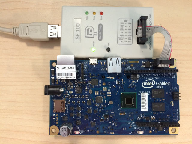
Once the sources have been downloaded, an EDK II build environment established, and an EDK II firmware image has been built, the EDK II firmware image needs to installed into the FLASH device on the target Galileo development board. One way to do this is with the Dediprog SF100 IC Programmer.
Install the DediProg SF100 software.
Connect the DediProg SF100 to the Galileo development board.
Make sure dpcmd.exe is in PATH
PATH=%PATH%;"c:\Program Files (x86)\DediProg\SF100"
NOTE: It is recommended that the FLASH image that was shipped with the Galileo development board be read and saved before updating FLASH image. The command shown below read the FLASH image and saves it to the file called GalileoOriginalFirmware.bin.
dpcmd.exe -r GalileoOriginalFirmware.bin
Update FLASH image using either the DediProg SF100 GUI or dpcmd.exe.
Example update of Galileo firmware image when BUILDTARGET is DEBUG (default)
dpcmd.exe -u%WORKSPACE%\Build\Quark\DEBUG_VS2015x86\FV\QUARK.fd
Example update of Galileo firmware image when BUILDTARGET is RELEASE (-b RELEASE)
dpcmd.exe -u%WORKSPACE%\Build\Quark\RELEASE_VS2015x86\FV\QUARK.fd
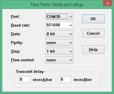
After the FLASH is updated on Galileo, a serial cable is connected between the host system and the Galileo target. A serial terminal emulator (such as Tera Term) can be used to see the logging messages from DEBUG() macros and the serial console for the UEFI Boot Manager, UEFI Shell, and operating system.
The default serial communication parameters for the Intel(R) Galileo Gen 2 Development Board is 921600,n,8,1 with no hardware flow control.
The default serial communication parameters for the Intel(R) Galileo Development Board is 461800,n,8,1 with no hardware flow control.
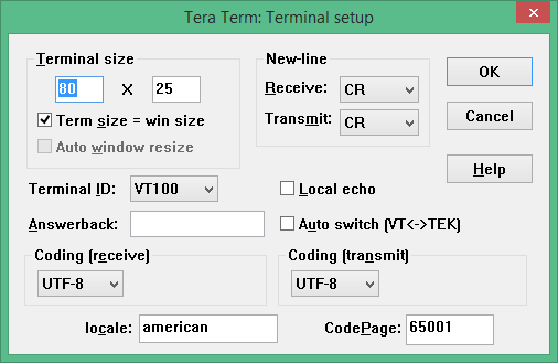
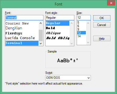
The following changes to the Tera Term configuration files are recommended for UEFI serial console compatibility. Some of the later use cases involve using the TCPIP mode, so some of these recommendation apply to the TCPIP use cases.
; Line at a time mode
EnableLineMode=off
[VT function keys]
;F6 key
;F6=64
;F7 key
;F7=65
;F8 key
;F8=66
;F9 key
;F9=67
;F10 key
;F10=68
[X function keys]
; F1 key
XF1=off
; F2 key
;XF2=60
XF2=off
; F3 key
;XF3=61
XF3=off
; F4 key
;XF4=62
XF4=off
; F5 key
;XF5=63
[User keys]
User1=59,0,$1B[M
User2=60,0,$1B[N
User3=61,0,$1B[O
User4=62,0,$1B[P
User5=63,0,$1B[Q
User6=64,0,$1B[R
User7=65,0,$1B[S
User8=66,0,$1B[T
User9=67,0,$1B[U
User10=68,0,$1B[V
Connect power adapter to Galileo development board, and the logging messages should be seen, followed by 5 second countdown, followed by an automatic boot to the built-in UEFI Shell.

Follow instructions in Intel(R) UEFI Development Kit Debugger Tool User manual to setup host system.
Build a firmware image with SOURCE_DEBUG_ENABLE enabled (-D SOURCE_DEBUG_ENABLE). This will select the appropriate libraries, debug agent, and PCDs for Galileo. Galileo does not support a USB 2.0 debug port, so only the UART based communications library is used.
Use Dediprog SF100 to update the Galileo development board FLASH image.
Update the [Debug Port] section of the SoftDebugger.ini file with the host side UART configuration settings. The following example uses COM5, which must be updated with the COM port the Galileo target is attached. The following example also shows a baud rate of 921600 which is correct for a Galileo Gen 2. If a Galileo Gen 1 is being used, set the baud rate to 460800. By default, the Galileo console is redirected to TCPIP port 20715.
[Debug Port]
Channel = Serial
Port = COM5
FlowControl = 0
BaudRate = 921600
Server =
Connect power adapter to Galileo development board and run a command script with the contents below to start a Tera Term session on TCPIP port 20715 and start the Intel(R) UEFI Development Kit Debugger Tool using UART connection between the host and target and WinDbg. The REBOOT button on the Galileo development board may need to be pressed for the debugger to perform the initial connect.
start "Console" /B "c:\Program Files (x86)\teraterm\ttermpro.exe" localhost:20715 /nossh
start "Debugger" /B "C:\Program Files (x86)\Intel\Intel(R) UEFI Development Kit Debugger Tool\eXdi.exe" /LaunchWinDbg
The figure below should be seen when a connection is made. The SoftDebugger Debug Console window shows the status of the connection between the host and the target. The Tera Term window shows the console output from the SEC phase until the debug agent is initialized. The WinDbg window shows that the debugger is connected and the WinDbg application can be used for run control, breakpoint management, and viewing call stacks, local variables, global variables, etc.

Setup hardware and software components following the instructions in the article at: https://software.intel.com/en-us/articles/using-intel-system-debugger-with-openocd
Connect power adapter to Galileo development board.
The following batch file starts Tera Term serial console on COM5 at 921600 baud, starts OpenOCD using a Flyswatter2, and starts Intel(R) System Studio Debugger. Select the Connect button to complete the host to target connection.
set OPENOCD="C:\Program Files (x86)\IntelSWTools\system_studio_for_windows_2016.0.023\debugger\openocd"
start "Console" /B "c:\Program Files (x86)\teraterm\ttermpro.exe" /C=5 /BAUD=921600
start "OpenOcd" /B %OPENOCD%\bin\openocd.exe -f ..\scripts\interface\ftdi\flyswatter2.cfg -f ..\scripts\board\quark_x10xx_board.cfg
call "C:\Program Files (x86)\IntelSWTools\System Debugger 2016\system_debugger\start_xdb_gdb_remote.bat"
When Reset Target is selected, the Galileo development board does not always halt at the first instruction at the reset vector. If debug is required from the first instruction of the reset vector, then update the file UefiCpuPkg/SecCore/Ia32/ResetVector.asm and change the two NOP instructions at the label ResetHandler: to JMP $. This puts the CPU into a wait loop until the debugger is connected and the debugger is used to set instruction pointer to the next instruction.
;
; For IA32, the reset vector must be at 0xFFFFFFF0, i.e., 4G-16 byte
; Execution starts here upon power-on/platform-reset.
;
ResetHandler:
;    nop
;    nop
    jmp $
ApStartup:
    ;
    ; Jmp Rel16 instruction
    ; Use machine code directly in case of the assembler optimization
    ; SEC entry point relative address will be fixed up by some build tool.
    ;
    ; Typically, SEC entry point is the function _ModuleEntryPoint() defined in
    ; SecEntry.asm
    ;
    DB      0e9h
    DW      -3
Connect power adapter to Galileo development board and boot to the UEFI Shell.
From the UEFI Shell execute the following commands to copy the GRUB EFI boot loader to \efi\boot\bootia32.efi. This allows the UEFI Boot Manager, on all future boots, to auto detect that the Micro SD FLASH device is bootable.
Shell> connect -r
Shell> map -r
Shell> fs0:
FS0:> mkdir efi
FS0:> mkdir efi\boot
FS0:> cp grub.efi efi\boot\bootia32.efi
The GRUB boot loader is set to a UART baud rate of 115200. A couple changes are required to change the baud rate to 460800 for Galileo Gen 1 or 921600 for Galileo Gen 2. From the UEFI Shell, execute the following commands to make a backup copy and edit the GRUB configuration file.
FS0:> cp boot\grub\grub.conf boot\grub\grub.conf.org
FS0:> edit boot\grub\grub.conf
title Clanton SVP kernel-SPI initrd-SPI IMR-On IO-APIC/HPET NoEMU
kernel /bzImage root=/dev/ram0 console=ttyS1,115200n8 earlycon=uart8250,mmio32,$EARLY_CON_ADDR_REPLACE,115200n8 reboot=efi,warm apic=debug rw LABEL=boot debugshell=5 rootimage=image-full-galileo-clanton.ext3
exit command to exit from the UEFI Shell and return to the UEFI Boot Managerroot. No password is required.vi to edit /etc/inittabS:2345:respawn:/sbin/getty 115200 ttyS1
/etc/inittabreboot -f to shutdown Linux and reboot the platform.After these changes both the EDK II firmware and the Linux operating system use the same baud rate.
The ACPI S3 Sleep and Resume feature can be tested on a Galileo development board using the Real Time Clock (RTC) for a wake event. The shell script shown below arms the RTC wake alarm 10 seconds in the future and puts the system to sleep. A shorter time in seconds can be passed in as the first argument to the script, but do not use times shorter than 2 or 3 seconds.
NOTE: The stmmac module is unloaded because the module is not compatible with S3 resume.
#
# Unload NIC driver that causes S3 to fail
#
rmmod stmmac

#
# Disable RTC wake alarm
#
echo 0 > /sys/class/rtc/rtc0/wakealarm

#
# Compute wake time that is $1 seconds in the future
#
let WakeTime=`date '+%s'`
echo $WakeTime
if ["$1" = ""]; then
  let WakeTime=$WakeTime+10
else
  let WakeTime=$WakeTime+$1
fi
echo $WakeTime

#
# Enable RTC wake alarm $1 seconds in the future
#
echo $WakeTime > /sys/class/rtc/rtc0/wakealarm

#
# Put systems into ACPI S3 sleep state
#
echo mem > /sys/power/state
Build a firmware image with SECURE_BOOT_ENABLE enabled (-D SECURE_BOOT_ENABLE). This builds in support for UEFI authenticated variables, UEFI image verification, and UEFI Secure Boot configuration screens in the Device Manager. In order to change the UEFI Secure Boot configuration, the user must assert physical presence. The Galileo development board only has two push buttons (REBOOT and RESET). The REBOOT button unconditionally reboots the platform. The RESET button asserts the reset signal on the Arduino header and is also connected to a GPIO pin, so the state of the RESET button can be read. The user asserts physical presence by holding the RESET button while the Galileo development board boots, or by holding the RESET button while selecting the Secure Boot Configuration option in the Device Manager.
Use Dediprog SF100 to update the Galileo development board FLASH image.
Connect power adapter to Galileo development board and boot to the UEFI Boot Manager by pressing F2 or running the exit command from the UEFI Shell. Select Device Manager and thenSecure Boot Configuration. Change Customize Secure Boot to Customized and then select Custom Secure Boot Options. If Custom Secure Boot Options can not be selected, then physical presence was not asserted using one of two methods listed above. Assert physical presence and try again.
The Custom Secure Boot Options screen allows the Galileo development board to be enrolled into UEFI Secure Boot. See How to Sign UEFI Drivers & Application V1.31 in the SecurityPkg Wiki for details on how to complete the UEFI Secure Boot enrollment.
Build a firmware image with MEASURED_BOOT_ENABLE enabled (-D MEASURED_BOOT_ENABLE) and TPM_12_HARDWARE set to ATMEL_I2C (-D TMP_12_HARDWARE=ATMEL_I2C). This builds in the TCG PEIM and DXE modules and uses the library for the Atmel I2C TPM hardware device.
Use Dediprog SF100 to update the Galileo development board FLASH image.
Attach the CryptoShield to the Arduino header of the Galileo development board as shown below.

Connect power adapter to Galileo development board and boot to the UEFI Shell. In the boot logging messages, messages similar to the following should be seen as the Atmel I2C TPM hardware device is detected and used to measure the contents of firmware volumes and firmware tables.
Loading PEIM at 0x0000FC75188 EntryPoint=0x0000FC75260 TrEEConfigPei.efi
PROGRESS CODE: V03020002 I0
TrEEConfiguration.TpmDevice from Setup: 1
DetectTpmDevice:
TpmDevice final: 1
TpmDevice PCD: 8B01E5B6-4F19-46E8-AB93-1C53671B90CC
. . .
Loading PEIM at 0x0000FC70190 EntryPoint=0x0000FC70260 TcgPei.efi
PROGRESS CODE: V03020002 I0
Install PPI: E9DB0D58-D48D-47F6-9C6E-6F40E86C7B41
Install PPI: A030D115-54DD-447B-9064-F206883D7CCC
PROGRESS CODE: V03020003 I0
The FV which is measured by TcgPei starts at: 0xFFF10000
The FV which is measured by TcgPei has the size: 0xF0000
The FV which is measured by TcgPei starts at: 0xFFD00000
The FV which is measured by TcgPei has the size: 0x1E0000
. . .
Loading driver at 0x0000F620000 EntryPoint=0x0000F620260 TcgDxe.efi
. . .
TPM TcgDxe Measure Data when ReadyToBoot
See the SecurityPkg Wiki for additional details on EDK II TPM support
Build a firmware image with PERFORMANCE_ENABLE enabled (-D PERFORMANCE_ENABLE). This builds in the UEFI Shell and the DP.EFI (Dump Performance) into a firmware volume and also includes a simple file system driver for firmware volumes so the DP.EFI command can be run out of the FLASH.
Use Dediprog SF100 to update the Galileo development board FLASH image.
Connect power adapter to Galileo development board and let it boot to the UEFI Shell. Then use the REBOOT button or the reset UEFI Shell command to reboot the Galileo development board. The first boot after a FLASH update does extra work that is only performed one time. In order to get correct performance measurements, use the 2nd or later boots. After the 2nd boot, run the dp -s command. The output should look similar to the figure below.
